After joining the Neato Connected Discord I ran into another smart banana (4_Fools) that proposed hiding the ESP32 behind the bumper and running a ribbon cable to the debug port like so:
So I plonked a Seeed ESP32-C6 (since they are known for quality HW, especially when speccing the internal antenna) and a generic 4P 0.1" female socket into the SolidWorks assembly and yea this looks like the best way to go, as it's a plug & play mod that (hopefully) does not require any modifications to the bumper:
Next step is to figure out the flex shape and reach out to JLCPCB for their flex, rigid stiffener, & adhesive spec.
First and last post of 2025... We on toddler time now fam :D
ISSUE:
Now that Neato has finally kicked the bucket (and all robot vacuums of their
servers), our much loved D5 has become a bit less useful. We can still push the power button to start a manual (and unoptimized) route, but can't do so remotely... So no more vacuuming the house twice when we are out and about D:
IMMEDIATE FIX:
Continue using manual route until... (see below).
PROPOSAL:
Luckily some very smart bananas (Philip2809) have figured out that you can control the D5 (and many other models) via the debug port with the help of an ESP32 & Home Assistant. Currently interfacing to the debug port is done in two ways, the first looking quite cyberpunk and the latter requiring you to disassemble the whole robot:
But I though, why not have a bit more fun with it and design my own rigid-flex PCBA that sits nicely on the bumper. Initially I was thinking of placing
the PCBA and cover on the top of bumper and running the flex underneath, but I
soon found that there is a pinch point where the flex would exit. Plus
there would be some tight bend radiuses which are far from ideal for a continuously (though minor) moving assembly:
Then I though about placing it on the side (position 2 below), but this would
mean the right side of robot would not be able to run as close to the wall as
before. So the next best position is at the front of
the bumper, directly above the debug port (position 3 below). Sure this loses
a bit of front bumper space, but it does mean the flex region of PCBA is short
and does not have any complex bends:
DECISION:
Front of bumper (position 3) it is. Next step, figure out rigid-flex PCBA
constrains from my very crude 3D scan (which you can get here):
After many late nights and long train rides the
AR2 Barrel
electronics are complete! For those curious the electronics assembly consists
of 4 PCBAs:
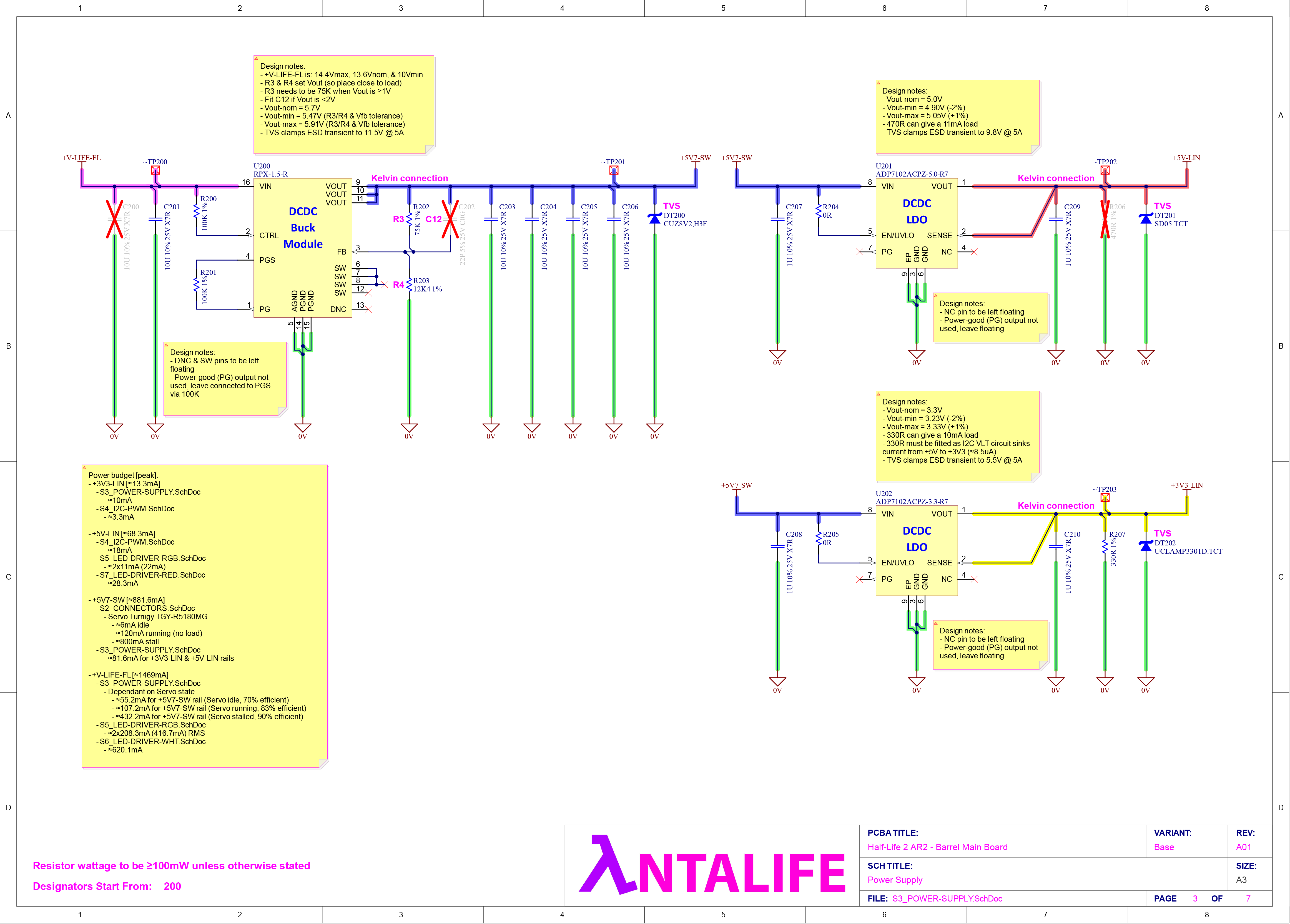
BARREL_MAIN-BOARD
The Big Boss
Holds various switching & linear regulators that power servo &
RED/WHT/RGB LEDs
LED brightness/colour & servo position are controlled with PCA9685PW, which itself is controlled via I2C
Lastly, as this is the main gateway to other PCBAs (one of which will be
over a long cable...), the board has additional filtering & protection
to improve EMI & ESD performance
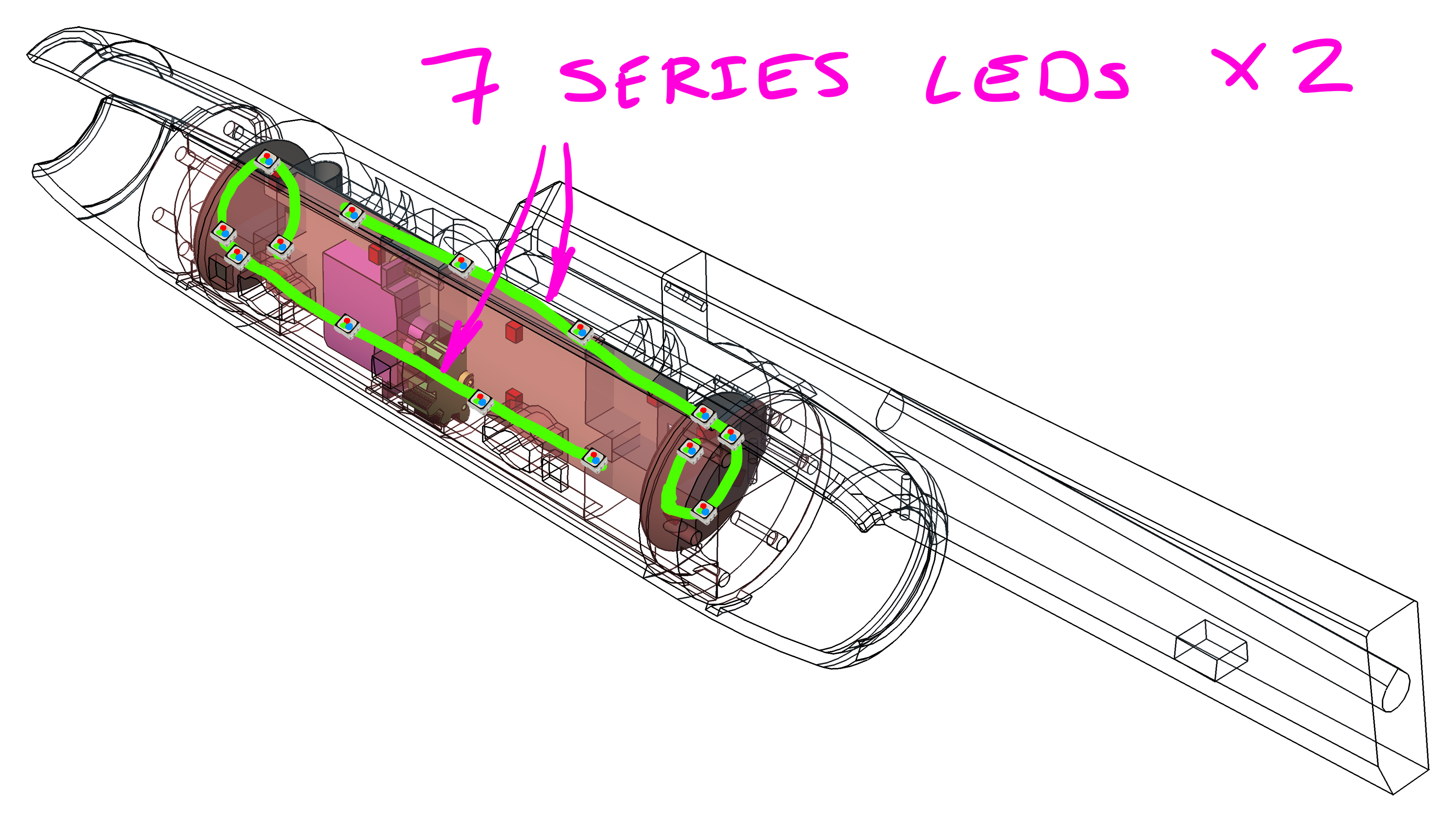
BARREL_LED-CARRIER-CENTRE
Holds a pair of RGB LED chains for barrel glow effect
Interfaces to front & rear PCBAs
Has some really cool artwork on the silkscreen/overlay ;^)
Holds RGB & RED LEDs for barrel & shell glow effect
And here's how the AR2 Barrel MECH & ELEC assembly looks like:
Deep-dive into BARREL_MAIN-BOARD PCBA
Just like with the RECEIVER_MAIN-BOARD
I want to give a quick rundown of what I am happy with and what I know
could be better (you know... have I had more time). But before getting
into the nitty gritty here is a cool timelapse of the board
being laid out in Altium:
The Good
1. GOOD, Solid 0V reference plane for high energy switching zones
All of my switching regulators and complementary EMI filters are located
on the bottom side, away from the "sensitive" digital zones on top layer.
~0.2mm below the bottom layer I have a solid 0V reference plane, ensuring
that the high energy current traces have a closely coupled return path
(think small current loop area, translating to lower emissions)
And for those tracks that change their reference plane (as in jump from
bottom to top layer), I make sure to use a 1N stitching capacitor to
assist with the return path. More on this in the BAD section
Previously
I was using 0603 sized ceramic capacitors for decoupling, filtering, &
general bulk storage. A downside of such a "small" package (depending who
you ask) is that with a typical X5R/X7R dielectric the
capacitance will be dependant on bias voltage (and temperature), something most manufacturers don't show in their
datasheet:
NOTE: Electrolytic & tantalum capacitors also have this
behaviour, and from memory polymer versions of the two are not as impacted.
But as always you need to check the datasheet to know what to expect... as
you can get drastically different performance with same dielectric material
Is this a problem? As always, it depends on the application. But here are a
couple of solutions/scenarios if I wanted to stick with using a ceramic
capacitors:
Use a dielectric that is "independent" on bias voltage or package
temperature, like C0G/NP0. This is the way to go when precision is
required (say an active filter), BUT be wary that getting a C0G capacitor
that is >100N is going to get expensive
Use a physically larger package (1206 instead of 0603) as having more bulk
material assists with bias & temperature behaviour, BUT as you can
expect this is at the cost of additional board space. Luckily for me I had
plenty of that, so I just upped the package size:
1. BAD, Top side tracks have a poor reference plane
I am very happy with my 0V reference plane (bottom side tracks), but I
don't have the same enthusiasm for the reference plane used by the top
side tracks... as the thing is incredibly choppy:
What does this mean? Well I can expect to see increased emissions, as the
return current for each trace can no longer run directly underneath. James Pawson of Unit 3 Compliance has a really good video on this, but below are some key slides to
explain the issue:
To help this discontinuity in return path I have sprinkled as many reference
plane stitching capacitors as I can across the board. But now that I think
of it I should have just poured 0V on the top side and stitched it to the
internal 0V reference plane with a matrix of vias, spaced to reflect the
highest frequency of concern
2. BAD, LED connector positions could be better
Though I am quite happy with the tight layout on the bottom side, once the
LED related nets make their way to the top side the trace lengths become
unpleasantly long due to the connector positions. Again I can expect
increased emissions due to the larger loop area D:
An easy solution would be to move the connectors (not possible), or throw
more layers at the board
3. BAD, EM zone boundary filters could still be better
J101 could easily have a common mode choke on all 3 data lines, as each pin
has a 0V conductor next to them...
J102, P100, & P101 do not have a filter at all... So expect worse
emissions (EM noise getting out) & susceptibility (EM noise getting in)
performance here
Schematic & PCBA
And to close it all off, here are the BARREL_MAIN-BOARD schematics:
Not long ago a mate of ours got a puppy and wanted to give "voice training" a
go. For those unfamiliar, this is when you teach your pet to push a button
corresponding to an activity they want to do, like in this amusing video:
After a bit of online searching they saw that FluentPet had a rather expensive button kit, so asked us if we would be keen to give them a hand making a DIY "voice board". We said yes and decided to make a mini one for our cat with whatever spare parts remained :D
So below is how our mini "voice board" compared to our CAD model, and for those curious how it was all wired up inside:
The last few months have been quite the rollercoaster for us, from
Putin's unjust invasion of Ukraine, to me starting a new job... And only recently have I had the headspace to
get back to the AR2
So in this quick update I want to show yous the revised
RGB LED driver configuration. Basically I will be halfling the barrel LED zones from 4 (2x3S & 2x4S)
to 2 (2x7S). Doing so reduces the complexity of the barrel PCBA's (like
halfling the RGB LED driver IC's from 4 to 2, and lowering the LED connector
pin-count from 28P to 16P), which is a welcome change as each RGB LED driver
(LT3496) goes for ~13AUD/pc in low quantities
Now you might be asking, why not just drive all the 14 RGB LEDs in a big
series configuration? Well I tried to simulate this scenario and soon realised
that the forward voltage drop for the big LED chain would be too much for
the LT3496 (who's SW pin is rated to 45V). I should also mention that I
configure the OVP (Over-Voltage Protection) to 35V, so anytime the SW pin goes
beyond this the IC shuts down for that switching cycle. Lastly below is the
total forward voltage drop of each LED chain, and as you see in both cases we
are over the 45V/35V limit:
RED ⇒ 2.6Vf * 14 ⇒ 36.4Vf-tot
GRN/BLU ⇒ 3.5Vf * 14 ⇒
49.0Vf-tot
While if we break up the chain into half (2x7S) we are nicely under the limit:
RED ⇒ 2.6Vf * 7 ⇒ 18.2Vf-tot
GRN/BLU ⇒ 3.5Vf * 7 ⇒ 24.5Vf-tot
So with all that out of the way, here are the latest simulations of the 2x7S
RGB LED configuration:
And here is an updated power losses & expected temperature rise (per IC)
table:
Couple of interesting things to note with above simulations/table:
I highly suspect that the LTspice model I am using for the BLU/GRN LED
is not the best as I am seeing massive ON/OFF & OFF/ON transients (like
in orders of 100's of mA). I am certain that the peak current would be more
closer to that of the RED LED simulation (~20mA above nominal), but to test
this I plan to place an inline 0R jumper which I will then use to measure
the actual peaks with a fancy oscilloscope at work
The RED LED channel is showing a higher power loss, this is due to the RED
LED current being double that of the GRN/BLU channel (40mA vs 20mA). So
think greater I²R losses
Guess who is back to crunching simulations in LTspice, this time trying to
figure out how well the
RGB LED driver
works ;^)
RGB LED, Configuration, & Driver Overview
The RGB LED I have decided to use is the
BROADCOM ASMT-YTD7-0AA02, which also comes with a diffused silicone cap to mix the emitted
light
The LEDs will be divided into 4 zones/strings inside the AR2 Barrel:
Finally, after comparing LED drivers like
HV9980,
LT3597,
LP5009... I decided to settle on the
LT3496
to drive the above configuration. The thing that makes this driver special
is that it has a Buck-Boost mode, which is a must when the nominal battery
voltage hovers close to the total forward voltage of the LED sting
(particular for the GRN & BLU channels). Below is the LTspice simulation
for the RED string:
Reducing the current sense voltage (CTRL pin) from 100mV to 50mV lowers
the peak LED current during ON-OFF transition from 110mA to 80mA (think
reducing swing range of error amplifier). LEDs are rated for 100mA
peak 100ns pulse and though the 110mA pulse was only for 25ns, I really
wanted to be sure I am not hitting the 100mA maximum limit
Reducing the switching frequency from 2.1MHz to 1.25MHz improves converter
efficiency, as ON losses are lowered from 96mW to 76mW. Reducing the
frequency beyond this brings diminishing returns, as losses are more or
less ~70mW, while LED ripple current is increased (for same size
inductor, 10μH)
Chosen VC filter (22K & 470P) helps minimize LED current overshot and
improves settling time (during OFF-ON transition)
OVP resistor divider sets the LED string over-voltage protection to 35V.
So if in the unlikely scenario that say a single LED fails in the RED
string, the string will be safely shutdown to make sure it does not impact
the GRN/BLU strings
RGB LED in Detail (Or Why We Need a Buck-Boost Mode)
Remember when I said having a
Buck-Boost mode is super useful when the nominal battery voltage hovers
close to the total forward voltage of the LED sting? Well lets look at this
in more detail... First off I will be using a 4S LiFePO₄ battery, so I expect the
voltage to be:
14.4V maximum
13.6V nominal
10.0V minimum
I plan to drive each LED channel at 80% maximum DC current rating, so I
expect the individual forward voltage to be:
RED 2.3Vf nominal @ 40mA, & a maximum of 3.0Vf
GRN 3.1Vf nominal @ 40mA, & a maximum of 3.6Vf
BLU 3.1Vf nominal @ 40mA, & a maximum of 3.6Vf
So with a 3 series LED string the forward voltage will be:
RED 6.9Vf nominal & 9.0Vf maximum
GRN
9.3Vf nominal & 10.8Vf maximum
BLU
9.3Vf nominal & 10.8Vf maximum
And with a 4 series LED string the forward voltage will be:
RED
9.2Vf nominal & 12.0Vf maximum
GRN
12.4Vf nominal & 14.4Vf maximum
BLU
12.4Vf nominal & 14.4Vf maximum
Note how the LED string forward voltage spans the range of the battery
voltage, meaning we can't just use a Buck or Boost regulator, as we will run
into cases where battery voltage is too high/low for regulator to function.
This is exactly where the Buck-Boost mode saves the day, as it can happily
regulate the string voltage to required value :D
Linear vs Switching (Or When Things Get Hot)
So first of all we can't use a linear regulator to drive 4 series LEDs,
unless we increase the
battery voltage (as it would need to be ~2V higher than maximum forward
voltage of the string). A linear regulator can just about drive 3 series
LEDs, as in this scenario the battery voltage mostly gives enough
headroom. With that said, lets compare how a linear regulator compares
to a switching one
NOTE: I am setting the LED string brightness with a 1kHz PWM
waveform that is at 50% duty
So using a switching regulator reduces the average dissipated power by
~70% (from 145mW to 40mW), and the ON dissipated power by ~80% (from
290mW to 56mW)... and that's just for the RED LED string/segment (as in
not including the GRN/BLU string)!
Next lets expand the simulation to include the GRN/BLU LED driver losses
and see what the expected IC (just the one, not the 4 I need to drive
all barrel zones) temperature rise above ambient is: