UPDATE: Turns out there is a cool website that can do all the hard-work for you, PrusaPrinters did a very good tutorial on how to use it
So a while back I found out that you could easily use a 3D printer to
make a lithophane. For those not familiar with the term think of a solid
object that varies in thickness in a particular way that it forms a
picture when light in shined though it, giving you something like:

It turned out that my partners birthday was also coming up, so I decided
to make a cube which held a number of pictures that would also be
illuminated by an RGB LED (see previous post).
The thing that I soon found was that calibrating the printer for making
these is quite a project in itself, as it must have taken me at least 20
prints (at various settings) before I could get a reproducible and working
piece. But with that said here is how I did it, so that you don't have to
suffer as much as I did:
- The very first step I'd recommend you do is calibrating your 3D printer, particularly making sure that your steps (X,Y,Z,E) and hotend temperature is within reasonable values. Thomas has a few awesome videos for this.
- Once you are happy with your printer download BMP2IGES, a super handy program used to make lithophane STL's.
- Before using BMP2IGES know this, the higher the resolution of your picture (pixels wise) the more difficult it will be to print it successfully. For example say I have a 0.4mm nozzle (use a 0.5mm extrusion width) and I want to print a 100mm by 100mm lithophane, what is the maximum resolution image that I can use? Well I found that setting the maximum "pixel" size of the lithophane at half your extrusion width gives good results. So with the 100mm by 100mm example the maximum resolution image I'd use is 400 x 400 pixels [100÷(0.5÷2)].
-
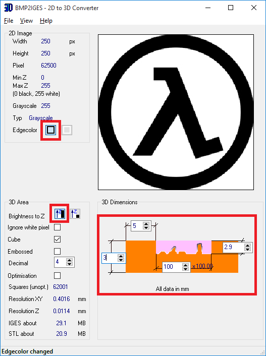
Next grab the image you want to use and resize it appropriately. Once
you've done that open up BMP2IGES and import the image by clicking
File -> Open. The picture below shows the parameters that I found to
work quite well. Feel free to play around with these though to see what
they do.

- Having set all that up next create the STL by clicking File -> Save&Calculate -> Save as STL. BUT before using the STL there is a high chance that it has some errors, so use a program like netfabb to repair it (here is a good video of how to repair STL's).
- Now that you have your good STL file import it into your favourite slicing software (I use Simplify3D myself). First major change you need to do is make the infill solid, as we don't want your fancy infill pattern interfering with the picture. I find that with my printer making the infill rectangular with a fill percentage of 85% does the job well. Also some people say that printing your infill at a lower angle (<30°) gives better results, but I found that 45° works just fine. Lastly the slower you print the better lithophane will come out to be, for me 50mm/s gave good results. Here is pictures of my printing settings, but since optimal values differ from printer to printer it's up to you to have a play around.
- Finally hit print and hope for the best ( ͡° ͜ʖ ͡°)
If you want to take this lithophane business one step further you could also make an enclosure box and place an LED in the centre to light it all up, kinda like the picture below:

You can get the model for the enclosure from here. I've also included the circuit schematic and code below. For my
project I decided to use the cheap and plentiful ATtiny13 (which I
programmed via my Arduino UNO with the help of
this
tutorial), but you can use any AVR micro you want as long as it has x3 PWM
outputs, x1 analog input, and x1 digital input.

NOTE: I found that limiting the forward current to ~220mA gives the best
compromise between brightness and heat produced.

/////////////////////////////////////////////////////////////////////////////////////////////
// RGB LED control - v1.2
//
//
//
// A simple program for controlling an RGB led with a single
potentiometer.
//
// As per I/O pins below, the RED pin of the RGB LED is connected to
pin #9 of the Arduino //
// GREEN pin to pin #10, and BLUE pin to pin #11. Also the output of
the potentiomenter is //
// located on pin #A0.
//
//
//
// ANTALIFE - 16.08.15
//
/////////////////////////////////////////////////////////////////////////////////////////////
//MUH I/O PINS
int R_pin = 1; //9 on
Arduino
int G_pin = 0; //10 on Arduino
int B_pin = 4; //11 on Arduino
int RGB_pot_pin = 3; //A0 on Arduino
int Rainbow_pin = 2; //8 on Arduino
//MUH VARIABLES
float theta = 0;
int colour = 0;
int rainbow_delay = 0;
void setup()
{
//MUH OUTPUTS
pinMode(R_pin, OUTPUT);
pinMode(G_pin, OUTPUT);
pinMode(B_pin, OUTPUT);
pinMode(Rainbow_pin, INPUT);
}
void loop()
{
//If rainbow mode enabled scroll through the rainbow ;^)
while (digitalRead(Rainbow_pin) == LOW)
{
for (float RAINBOW = 0; RAINBOW < 256; RAINBOW =
RAINBOW + 0.5)
{
//If rainbow mode disabled stop animation
if (digitalRead(Rainbow_pin) == HIGH)
{
break;
}
MUH_colour(RAINBOW);
delay(analogRead(RGB_pot_pin) +
rainbow_delay);
}
}
//If rainbow mode not enabled simply display the set
colour
theta = analogRead(RGB_pot_pin) / 4;
MUH_colour(theta);
}
void MUH_colour(int angle)
{
//This fucntion converts the given angle to a visible colour
on the colour wheel
//with RED being 0deg, GREEN being 120deg, and BLUE being
240deg
//RED TO GREEN [0deg -> 120deg OR 0 -> 85]
colour = (6 * angle) % 255;
if (angle <= 42.5)
{
RGB_write(255, colour, 0);
}
else if ((angle > 42.5) && (angle < 85))
{
RGB_write((255 - colour), 255, 0);
}
//GREEN TO BLUE [120deg -> 240deg OR 85 -> 170]
else if ((angle > 85) && (angle < 127.5))
{
RGB_write(0, 255, colour);
}
else if ((angle > 127.5) && (angle < 170))
{
RGB_write(0, (255 - colour), 255);
}
//BLUE TO RED [240deg -> 360deg(or 0deg) OR 170 ->
255(or 0)]
else if ((angle > 170) && (angle < 212.5))
{
RGB_write(colour, 0, 255);
}
else if ((angle > 212.5) && (angle < 255))
{
RGB_write(255, 0, (255 - colour));
}
}
void RGB_write(int R_val, int G_val, int B_val)
{
//A simple function that displays the desired LED colour by
setting the duty of the
//PWM on each RGB LED
analogWrite(R_pin, R_val);
analogWrite(G_pin, G_val);
analogWrite(B_pin, B_val);
}
And finally here is a video of it all working :D
This comment has been removed by the author.
ReplyDeleteFrom what I recall I got something like this https://goo.gl/wGbRft
DeleteYou can use a higher wattage just make sure the heat-sink is good enough.
What RGB package did you use?
ReplyDeleteNot sure what the package is called but you could use this to make the footprint https://goo.gl/K3NWEi
DeleteWhat about the wattage ratings for the potentiometers and resistors?
DeleteDon't need to be high wattage, just a generic 1/4W will do
DeleteOne last question: Will a 1 W RGB be sufficiently bright?
ReplyDeleteDunno, one way to find out ;^)
Delete